Kadee #5 Coupler Box Kadee #78 Coupler Box Accurail Proto Coupler Box
FIGURE A
You will need the following materials to assemble the kit:
| Pin Vise with: | |
| #50 drill bit to mount the truck screws and Kadee #5 coupler pockets | Body putty |
| #55 drill bit to mount Kadee #78 and Accurail Proto coupler pockets | Jewelers files |
| #68, #74 and #79 drill bits for the car body | Wire cutters |
| Jewelers screwdrivers | #11 hobby knife |
| ACC and styrene glue | Fine needle nose pliers |
WHAT'S INCLUDED IN THE KIT:
| Resin G31D Gondola Car Body | 2 18 Straight Grab Irons (part #13) |
| 3 Resin Grab Iron Brackets | 4 18 Drop Grab Irons (part #12) |
| Details West BS-1021 Brake Set | 2 16 Straight Grab Irons (part #11) |
| Accurail 0100 Bettendorf Trucks | 1 Piece 0.010 x 0.040 Styrene Strip |
| 4 Intermountain 33 metal wheelsets | 1 Piece 0.010 x 0.030 Styrene Strip |
| 2 3/16 2-56 Screws | 1 Piece 0.010 x scale 9 wide styrene Strip |
| 3 double-sided pages of instructions | 4 9 x 12 Stirrup Steps |
| 10 22 Long Straight Grab Irons (part #14) | 4 Styrene Tack Boards |
| 2 22 Drop Grab Irons (part #16) | 2 0.012 Brass wire Brake Platform Support |
| 4 18 Straight Bracket Grab Irons (part #10) |
PART NUMBERS USED IN THE DRAWINGS
| 1. Corner Cap | 12. 18 Drop Grab Iron |
| 2. End Grab Iron Support | 13. 18 Straight Grab Iron |
| 3. Brakewheel Housing Mounting Bracket | 14. 22 Straight Grab Iron |
| 4. Retainer Valve Pipe | 15. Right-Side Grab Iron Bracket |
| 5. Retainer Valve | 16. 22 Drop Grab Iron |
| 6. Brakewheel Housing | 17. Brake Platform |
| 7. Brake Chain and Rod | 18. 0.012 Wire Platform Support |
| 8. Fulcrum | 19. Bettendorf Trucks and Wheels |
| 9. 3/64 Angle | 20. Stirrup Steps |
| 10. 18 Straight Bracket Grab Iron | 21. Brake Wheel |
| 11. 16 Straight Grab Iron | 22. Tack Board |
1. Inspect the gondola body - fill in any air holes with putty and sand smooth.
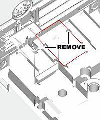
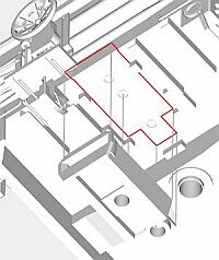
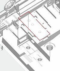
2. If you are going to use Kadee #5 style coupler boxes the round mounting lugs on each side of the box must be cut off and two small blocks must be carved off the bottom of the gondola body. Kadee #78 and Accurail Proto coupler boxes will drop into place. The coupler boxes will be installed later on. (see FIGURE A)
Kadee #5 Coupler Box Kadee #78 Coupler Box Accurail Proto Coupler Box
FIGURE A
3. Glue the 9 x 11 pieces of 0.010 styrene (part 1) to the four outer corners on the top of the gondola body (make sure the two outside edges overhang the car body by 0.005). Round off the top of the two outside faces of these caps. (FIGURE B)
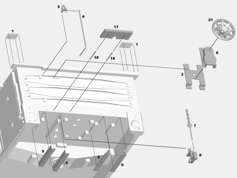
FIGURE B
4. There are holes cast into the gondola body where the grab irons and stirrup steps will be mounted. Drill out all the holes for the grab irons on the gondola body with a #79 drill. Use a #74 drill for the stirrup step mounting holes. The two right-side grab iron brackets (part 15) need to have the three pilot holes in each piece drilled out with a #79 drill. (see FIGURE C)
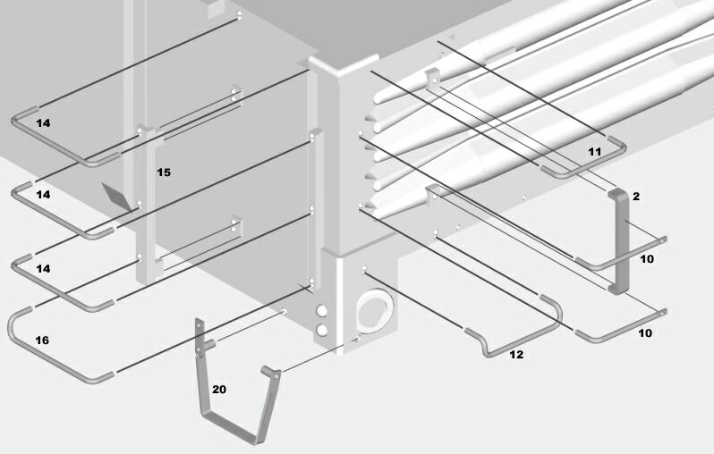
FIGURE C
5. Glue the two brass grab iron supports (part 2) between the mounting lugs on the car ends. (FIGURE C)
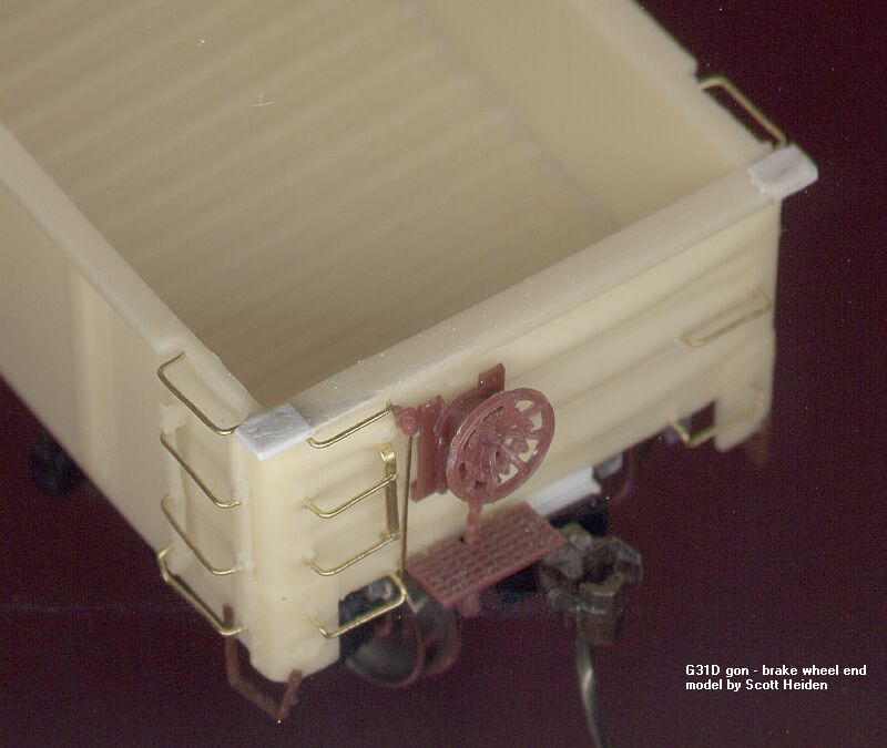
6. Glue the brakewheel housing mounting bracket (part 3) to the end of the car with the rectangular mounting lug cast into it. The bottom face of the mounting lug rests against the top of the bar in the middle of the mounting bracket and the mounting bracket is shifted to the right until it hits the left side of the mounting lug. There should be a scale 3 gap between the grab iron support (2) and the mounting bracket (3). (FIGURE B)
7. Slide the 0.012 retainer valve pipe (part 4) into the retainer valve (part 5) but dont glue them together yet. Position them to the left of the brakewheel housing mounting bracket (3) and mark the point to drill a #74 hole in the gondola body for the retainer valve mounting lug. (FIGURE B)
8. Drill the #74 hole and glue the retainer valve (5) and pipe (4) to the gondola body. The bottom of the retainer valve pipe (4) should rest against the bottom of the gondola body. (FIGURE B)
9. Glue the brakewheel housing (part 6) to the brakewheel housing mounting bracket (3). Place the brakewheel housing (6) on the mounting bracket (3) so the mounting pin on the brakewheel housing goes below the bar in the middle of the mounting bracket. (FIGURE B)
10. Slide the brake chain and rod (part 7) into the fulcrum (part 8) and test fit them into the brakewheel housing (6) to locate where to drill a #68 mounting hole in the bottom of the body for the fulcrum. You may have to remove 2 or 3 links of chain from the top of the brake rod. The fulcrum should be roughly centered on the rib behind it and the front lip should protrude 0.010 past the edge of the car bottom. If you are using Kadee #5 coupler boxes, temporarily mount the coupler box to make sure the fulcrum isnt set in too far towards the centerline of the car. (FIGURE B)
11. Take the eight pieces of 3/64 angle (part 9) and thin down the thickness of the visible ends by lightly filing the inside faces until half the inside edge is removed. With the bottom legs of the angles pointing toward the center of the car body, glue these angles (9) to the four blocks cast into the car bottom with the filed ends of the angles sitting even with the end of the car. The piece blocked by the brake fulcrum (8) can be glued in butting up against the back of the fulcrum or you can remove 6 of the bottom leg so the side of the angle can slide past the fulcrum to the end of the car. (FIGURE B)
12. Glue the 18 straight bracket grab irons (part 10) to the car end and the brass grab iron support (2). You could solder these grabs to the support for extra strength. Glue the 16 straight grab iron (part 11) into the holes at the top left corner of the car end, making sure it sticks out from the end the same distance as the grab irons below it. Glue in the 18 drop grab iron (part 12) into the holes in the bottom left corner of the end, making sure it sticks out the same distance as the other grab irons. Repeat these steps on the other end of the car. (FIGURE C)
13. On the right side of the car end, glue in an 18 drop grab iron (12) in the bottom right corner of the car (sticking out the same distance from the end as the grab to the left of it). Glue in an 18 straight grab iron (part 13) above the drop grab iron make sure it sticks out the same distance as the one below it. Repeat these steps on the other end of the car. (FIGURE D)
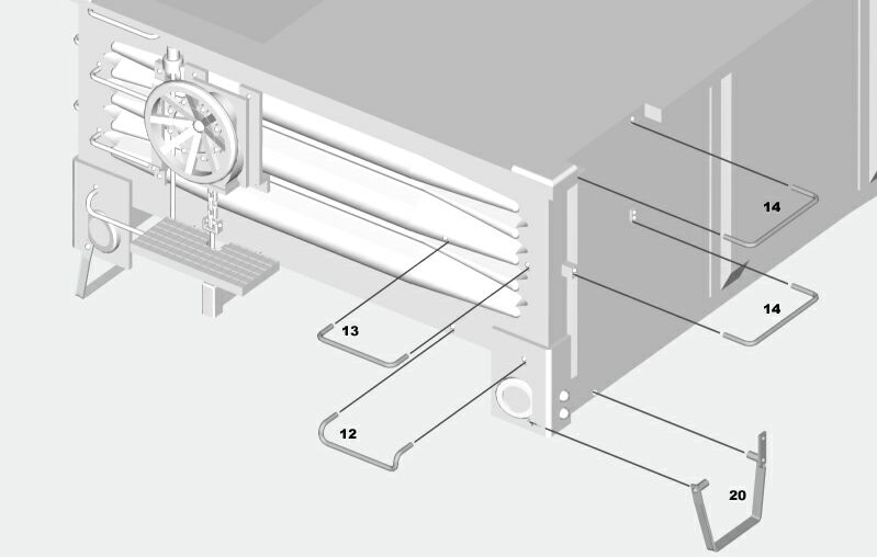
FIGURE D
14. On the left end of each car side, glue in a 22 straight grab iron (part 14) in the upper left set of holes. Glue a second 22 straight grab iron (14) in the holes below it. Use a piece of scale 6 x 6 to space the grab irons the right distance from the car side. Repeat these steps on the other end of the car. (FIGURE D)
15. Insert (dont glue yet!) the scale 22 straight grab iron (part 14) into the top hole of the right-side grab iron bracket (part 15), put the scale 6 x 6 spacer under the grab iron to set the distance from the car side,and trim the end of the grab iron flush with the bottom of the side grab iron bracket. Insert the other end of the grab iron in the second hole from the top on the right of the car side. Adjust the grab iron and the side grab iron bracket so they are perpendicular to each other and glue the side grab iron bracket to the mounting plates on the car side. Test fit and glue a 22 straight grab iron (14) in the middle holes, and a 22 drop grab iron (part 16) in the bottom holes. Once these are dry, glue the top 22 grab iron in place. Glue a 22 straight grab iron (14) in the top set of holes on the right side of the car, using the 6 x 6 to keep it at the same distance from the car side as the grab irons below it. Repeat these steps on the other end of the car. (FIGURE C)
16. Place the brake platform (part 17) against the end of the car to mark the drilling locations for the scale12 long 0.012 platform support wires (part 18). Try to center the hole in the brake platform on the brake chain and rod (7). Drill the #79 holes approximately 0.020 up from the bottom of the car. (FIGURE B)
17. I would recommend putting the couplers into their boxes and carefully gluing the boxes shut, then epoxying the assembled coupler boxes to the floor of the car rather than attaching them with screws. There is barely enough material to drill a hole in the car floor for a coupler screw without punching through the inside of the car floor. You may need to glue a .020 or .030 styrene spacer to the car floor to lower your couplers to the proper height (doing this will give you just enough material to screw your coupler boxes to the car). Add 3-4 ounces of weight to the bottom of the car where the car sides will hide it from view. (FIGURES A AND E)
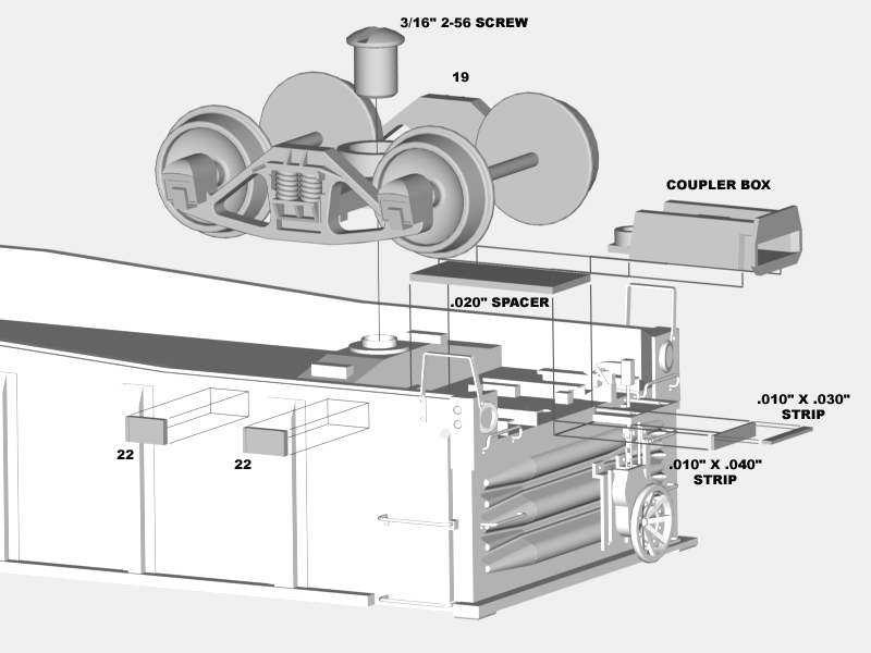
FIGURE E
18. Drill out the hole in each bolster with a #50 drill bit: be careful you dont drill through the car floor. Mount the trucks (part 19) to the car body with a 3/16 2-56 screw. The screw will tap the hole as it goes in. (FIGURE E)
19. Cut the pieces of .010 x .030 and .010 x .040 styrene into pieces the same width as your coupler pocket. Glue one piece of each size together at right angles to make a .040 x .040 angle. Glue this angle to the top of your coupler pocket with the vertical face pressed against the car end. (FIGURE E)
20. Cut the stirrup steps (part 20) off the sprue and CAREFULLY bend the left side mounting pin on TWO of stirrups 90 degrees inward. Bend the RIGHT SIDE mounting pin on the other two stirrups 90 degrees inward. Cut off the material on each of the turned legs above the mounting pin. Test fit the stirrup steps on the car body, then glue them in place. (FIGURES C AND D)
21. Glue the brake wheel (part 21) into the brakewheel housing (6). (FIGURE B)
22. Glue one tack board (part 22) roughly a scale 6 on either side of the first rib from the left end on each car side. One tack board is a scale 12 long; the other is 13. Judging from one photo I have, the larger one is mounted closest to the grab irons. (FIGURE E)
23. Wash the model, then paint and decal it.
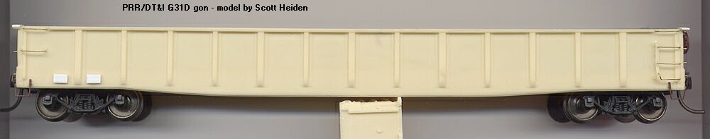
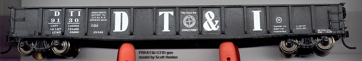
Here's a couple photos of an assembled car:
And this is what the test set of decals look like:
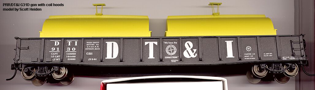
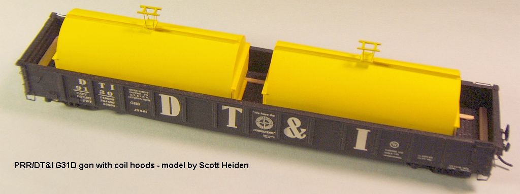
I built a set of coil hoods based on a photo from Fallen Flags:
Instuctions for building an auto frame rack for this car are here.