Rear Frame Rack
REAR FRAME
Using styrene cement, glue the bottom support brace (part 1) between the two sides (part 2). Use a machinists square to make sure the corners are square and the sides are perpendicular to your work surface.
Glue the top frame support (part 3) between the sides. The top frame support consists of a scale 121" long piece of 1/8" channel (part 3A) with a scale 111" long piece of 1/8" channel (part 3B) glued to the center of its back side. A scale 111" piece of 0.030" x 0.030" styrene (part 3C) is glued to the bottom of the smaller piece of 1/8" channel.
Using ACC, cement the 3 x 8 wood support (part 4) to the top frame support (3).
Using ACC, glue the large gusset plate (part 5) to the outside of each side. The small gusset plate (part 6) is glued on top of the large gusset plate (5) and recessed up under the top frame support (3).
Carefully slip the rear frame into the gondola body (it goes on the same end as the brake wheel) and glue it to the floor with the front edge of the bottom support brace (1) lined up with the gap between the third and fourth boards in the car floor.
Glue the 0.060" angles (part 7) to the top of the gon side where the side pieces meet the top of the gon sides.
Rear Frame Rack
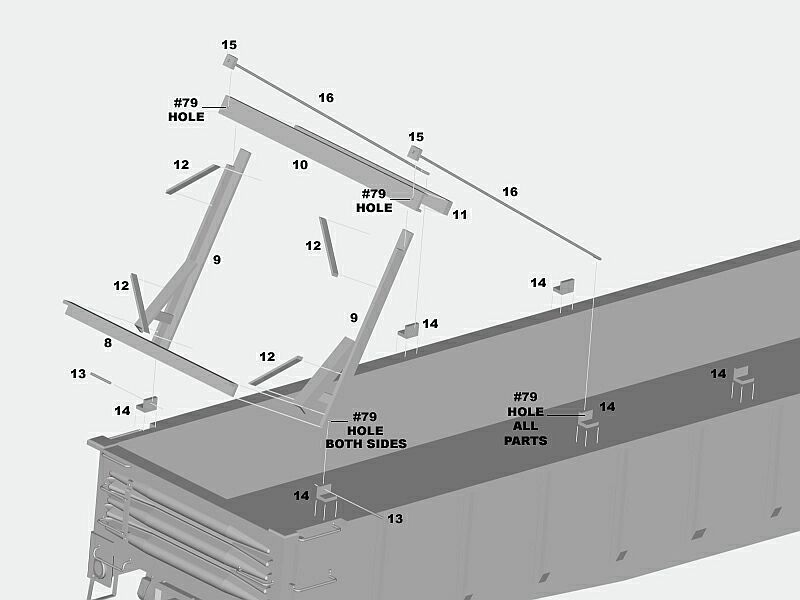
FRONT FRAME
Glue the bottom support brace (part 8) to the bottom of the side pieces (part 9). Make sure all the pieces are perpendicular to each other.
Glue the top frame support (part 10) to the flat spots at the top of the side pieces. Make sure this part extends past the side pieces an equal distance on each side.
Drill #79 holes in the top frame support at the center of the part that extends beyond the sides. Drill #79 holes in the side pieces at the bottom of each side. These holes should be located to allow the pivot pins (13) to be glued against the inside of the bottom support brace (8) where the two legs of the angle come together.
Using ACC, cement the 3 x 4 wood support (part 11) to the top frame support between the sides.
Using styrene cement, glue the 1 x 4 styrene diagonal braces (part 12) to the four inside corners of the front frame. The braces should be at a 45 degree angle to the sides.
Insert the 0.012" pivot pins (part 13) into the holes at the bottom of the front frame. They should project a scale 3 to 4 inches outside of the frame. Glue the pin to the inside of the bottom support brace with a tiny drop of ACC.
Take the six 0.060" angles (part 14) and drill a #79 hole in the center of the inside face of one leg in each piece. Slide one of these angles onto the pivot pin (13) on each side of the front frame.
Test fit this assembly on the top edge of the gondola. The inside face of the 0.060" angles (14) should be flush with the inside face of the gondola sides and the front frame should be able to rotate up and down without catching on the gondola sides. You may have to remove the angles and sand down the front frame sides at the bottom corners to allow the front frame to rotate without catching on the gon sides.
Drill a #79 hole in the center of the square 3 x 4 wood blocks (part 15) and glue one each onto the straight ends of the tie-down rods (part 16). The end of the tie-down rod should project about a scale 1" past the wood block.
Locating where to glue the 0.060" angles (14) to the top of the car side will depend on whether you want to model a car loaded with auto frames or an empty car. For an empty car, the two angles holding the front frame in place should be glued with the right edge of the angle (with the left side being the end of the gon) set back to the left about 3 to 4 scale inches from the right edge of the notch for the grab irons. The next pair of angles (14) are roughly centered between the third and fourth ribs from the left end of the gondola. The last pair of angles (14) are roughly centered between the fifth and sixth ribs from the left end of the gondola. All the angles sit flush with the inside of the gon sides.
Front Frame Rack
AUTO FRAME LOAD
I built a loaded car using auto frames made by JJM Railroad Enterprises (PO Box 1273 Elgin IL 60121). The car can hold 88 frames (two rows of 44 frames each) but JJM sells the frames in boxes of 80 frames each, so youll have to buy two boxes to do one car (eleven boxes of frames will do 10 loaded cars). I glued together two 44-frame rows that measured a scale 13 8" tall and test fit them into the gon (the back of the auto frame stacks should rest on the rear frame, and the front end of the stacks should almost touch the front of the car).
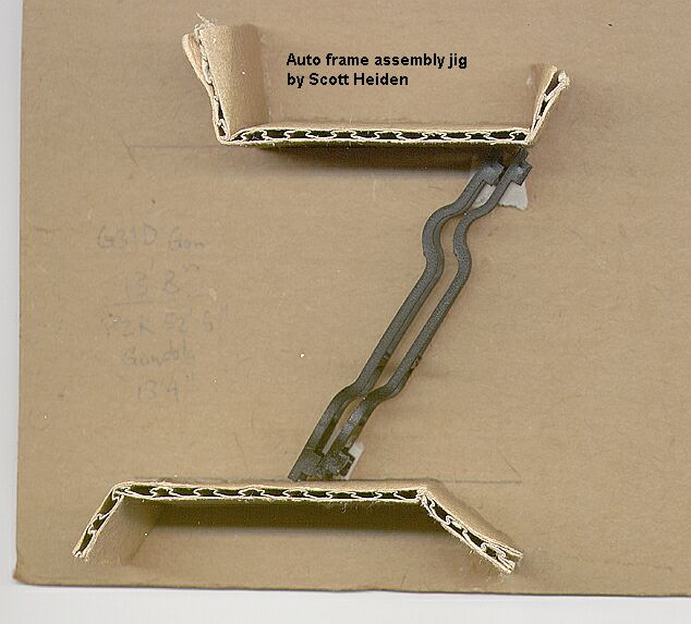
Assembly jig for JJM
auto frames
I test fit the front frame (with the angles press-fitted onto the mounting pins) on the top of the car, making it sit vertically parallel to the auto frame stacks and marked the location of the angles (14) on top of the car. Make sure the angles and the bottom of the front frame are horizontally parallel to the end of the car! I removed the auto frame stacks and (with the front frame press-fitted into but not glued to the angles) glued down the angles to the car side.
When the ACC securing the angles had set, I rotated the frame forward and put the auto frames back in the gon with their backs set against the rear frame. I pushed a wood 4 x 6 spacer into the middle of the rows (with the 6" side lying flat on the gon floor), and another wood 4 x 6 spacer on the outside of each row (with the 4" side lying flat on the gon floor).
I rotated the front frame back down until it made contact with the front of the auto frame stacks, and slid the tie-down rods (16) through the holes in the front frame. I put a 0.060" angle (14) on the bent ends of the tie-down rods (16) and marked where the angles sat on the car sides when the wood blocks on the ends of the tie-down rods were tight against the front frame. The angle should be roughly located between the third and fourth ribs from the left end of the gondola (and the tie-down rods should be near perpendicular to the front frame), but the location of the angle will vary depending on how the auto frame stacks were glued together (both of your auto frame stacks will be slightly different lengths). Glue the angles to the top of the car side flush with the inside of the gon and the same distance from the end of the car. You may need to add a wood shim between the front frame and the front of one of the auto frame stacks to keep the auto frames held firmly in place by the front frame.
I pressed a wood 4 x 6 spacer (6" side down) in between the two auto frame stacks with the ends of the 4 x 6 resting on the top of the front and rear frames to keep the auto frame stacks vertical. If the auto frame stacks lean outwards from the center of the car, take a piece of stiff wire (I use a staple) and bend two u-shaped clamps that will slide over the inside rails on the front and back of each auto frame stack and hold them tightly against the top wood 4 x 6 spacer.
By sliding the bent end of the tie-down rods out of the angles and rotating the front frame upwards, the auto frame load can be removed so you can send your gons back empty to Detroit. You may want to mark each auto frame stack with the car number and which side (left or right) it goes into the car since each stack will be slightly different in length.
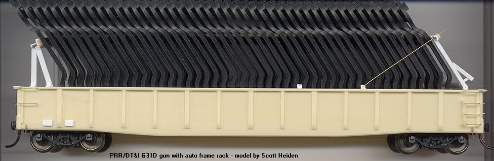
Assembled G31D frame gon kit loaded
with JJM Railroad Enterprises auto frames
Go
back to the Main Page
Go
back to the Modeling Articles Page